Showing posts with label autodesk. Show all posts

Concrete casting workshop


Yesterday i and Christina Lewis held a concrete casting at Bitraf.
The workshop was meant to be a collective tryout of concrete as material for both art and technology.
We used a thin, low viscosity concrete, intended for use as garage floors.


We did two rounds of castings, in the second round, we added colour in the concrete. The color was a challenge in it self, as adding any substance to the concrete, alters its properties. The one i ended up using, is a pigment in powder form, normaly used for painting chalk walls

For the big candle holder shown at the intro, i milled a mold from building insulation using a 10mm milling bit for removing the bulk of the material, then finishing it up with the 6mm long ball nose.


For the small project that we did over the weekend, using a drill mounted spiral mixer in a bucket where sufficient. For the molds, we used the already mentioned machined foam block, as well as cut bottles, coke cans, crumbled paper cups, and 3d printed molds.


The 3D printed molds where especially interesting, as the low viscosity concrete capture every minute details from the print.


More results from the workshop:


 If you want to try this out yourself, have a lookout for the next workshop at Bitraf's meetup.


Wooden screwdriver set


Even tho i am a big fan of mass production, the tray that my screw drivers came in was poorly moulded from crappy plastic. I decided to remake the tray in oak plywood and aluminium.
This was a good exercise in Autodesk Fusion 360 toolpath generation.


The brass screws where made from 8mm rod, and the slits where cut with a jewelers hacksaw. Then they where turned in the lathe so that they sit flush with the aluminium frame.


This is the toolpaths for the aluminium frame. it has roughing offsets, to make space for evacuating the chips from the cut.


This is where things gets complicated. The wooden tray is 3D milled. That means that the CNC machine is moving with all axises at the same time, to produce smooth edges with a round cutter.


Hexapod

Just testing the limit on how many components you can include in a 3D preview from Autodesk 360. Quite a few apearently. The explode view function is intresting.


largest aluminium part so far!

I manufactured my biggest part so far on the shopbot, a camera mount for taking FPV shots of the milling process. the part where designed in Autodesk fusion 360. 

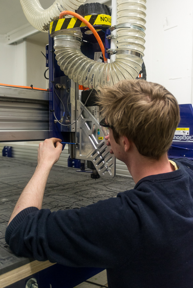
                           Here i am mounting the freshly made camera mount on our shopbot.


Using the slots in the mount, the camera can be positioned in several angels ensuring the best shot.


This bracket were cut using a singleflute carbide 6mm bit @18000 RPM, 10mm/sek and 2,8mm cut depth. The surface quality were sacrificed for a faster toolpath, clocking in at 1.45 hours.


Aluminium milling on the shopbot

There is a lot of misunderstanding out there regarding milling aluminium on CNC routers. i am sharing todays work with some data on feedrates and cutters that you can use as a baseline for doing similar work in your labs. The parts shown is for a ongoing work, my hexapod robot.

The first cut! as you see, these are quite deep pockets. when roughing out areas like these, the key is to always have a good chipload. meaning, that instead of going to slow and just rubbing the metal, go deep and remove it!

Here i took a cut of 7mm, removing 4mm the first pass, then 3,5, before the finishing pass where the last 0,5mm millimeter was removed. all this using a feedrate of 8mm/sek, with a singleflute 6mm carbide bit.
I maxed out the spindle at 18K rpm.

when you buy your bit, buy a upcut! A compression bit will leave good finish on wood, giving a smooth finish with out fraying. on aluminium however, the key is to evacuate the chips as fast as possible. an ucput bit will do just that, dragging the chips out of the cut.

A downcut will do the opposite, it will compress it it down in the cut you are leaving. Wile this works for the first pass, the cutter will break in the next, when you mill over all that compressed swarf.

Do you think you need to buy those expensive german made tools? No. they will last longer, they will give a better finish, but you will do just fine with cheap ebay tools when practicing.

On the long run however, the german and american made carbide tools are the more economic choice, as they can be ran at much higher feedrates, doing the job quicker.

A good tool will also leave a better finish, so that less work is left to do manualy. all the feeds and speeds i post are done with carbide mills. if you buy HSS tooling, i advise you to slow down a little.


This is a huge area that needed to be faced. when doing facing, you should be a bit agressive, so the chips are thrown away, so you dont mill over the chips you just cut loose. in my case, the vacuum system on the CNC mill was wery helpfull.

Here the deapth of cut where kept low at 2mm/sek, but at a higer feedrate of 15, which is realy pushing it when milling hard alloys like this.

Also, see the tiny holes? when drillling deliate features like this, activate peck drilling in vcarve.

This commands the shopbot to only go engage a certain depth of cut at once, then retreat to safeZ.

the depth it will use is set usingPassdepth at the cutter settings. this will break the chips, and avoid clogging the drillbit at the bottom of deep holes.
peck driling also reduces the chance of breaking delicate bit. in my case, the bit measured 2.1mm.

when dealing with tougher materials as aluminium, it is important to secure parts that will fall off, be cut loose or otherwise risk to be dragged into the cutting bit. not only would such an incident break an expensive bit, but can also cause serious injury as the cutter will often exceed speeds of 10K RPM.
when adding such screws, it is advised to make these holes in the vcarve file itself, so that you have specific controll over their position relative to other ares that will be cut.
If you drill these holdown holes by hand, the CNC will not be aware of their position, and may very well crash into them.


can you notice the stepped edge on the part being cut out?

when making deep cuts, you may clog the cutting bit, or risk welding the chips back onto the part itself. to avoid this, make an offset Pocket when making the first pass.

On the next pass, the cutter will not rub the previous edge, reducing workload, chatter and leaving room for clearing the chips. then, in the finnishing pass, make the cut at zero offset, so that you get a nice, shiny edge.

i have found that using climb cutting on both roughing and finishing, leaving 0,5-0,15mm is enough to achive a good finish, as leaving to little will result in rubbing, and a bad finish

For the finishing cut, a feedrate from 4-10 has given me sucsess, depending on the diameter of the cutter. as i mainly make small precise parts, i usualy use a 3mm upcut with one flute for finishing.


The freshly cut upper plate, with circuitboard and other parts mounted. When fitment of other components are determined, the plate will be removed, and the backside machined in a jig cut for the purpose.
I did not bother to do anything about the surface of the aluminium, but if you want to remove the pattern from the machining, a sanding pad with 800+ grid will do it in a few seconds.


This is the underside. for the servos to fit, i had to take a finnishing cut with the 3mm bit. The reason was that the 6mm bit left an excess radius, not alowing the servo to fully slide in. for this operation, i used the following data:

18000 RPM

1,5mm passdepth

5mm/s for feedrate

with a

single flute upcut 3mm carbide bit.

in comparison to the 3mm depth @10mm/sek with the 6mm bit, this went quite slow.

for other tools, you could use as a rule of thumb with pass depth: that you have 50% of the cutter diameter as max, meaning a 5mm bit would yield good results with 2,5mm as pass deapth.


The chips sould be quite rough and sharp. if they are tiny and flaky, or just like powder, you are not cutting agressively enough. That will wear your cutting tool down faster than using the right settings.
remember that milling will always create heat. you don't want that heat to stay in neither the cuttingbit or the material, you want to throw it away With the chips.
To be able to crete such large chips, it is importatant that you use a single or doube flute tool. As having more flutes increase the amount of material removed, you must also increase the feedrate, or lower the RPM to keep the amount of removed material constant.


The aftermath. These will be used to cast the other components of the hexapod. 

replicating viking jewelry

This piece were found hundreds of years ago, but made long before that, in year 900. The piece were digitized using a 3D scanner. The scan where then split in rhino, and the respective sides where then milled in wax, and fitting boxes for the sand mold where made.

The first step of a sand cast is to make the sand fine, you want no lumps in your mold! Here Jens Dyvik from Fellesverkstedet is preparing the mold.


This is one of the sides of the mold, together with the tools we will use to pack it with sand.


We left the tabs from the milling process of the mold frames, so that the sand will hold the mold better.


The first layer of sand is the most critical, so we powder the sand realy fine to catch all the details.


The sand must be packet realy hard. The blunt end of a hammer works just fine.


The two sides of a sand mold, complete with inlett and air wents.
for registration, we use 6mm dowels, normaly used in carpentry. We use a triangle pattern for registration, so there is no option to mount the molds together wrong.


Once the molds where ready, it was time to prepeare the metal, in this case salvaged from old harddrive cases.


We used the electric furnace to the rigth to heat the metal to 700 degres celcius.


here the metal has been poured. the sand contains quite a bit of oil to make it hold the pattern. This oil lets of some nasty fumes, so we use our fume extractor until the part has cooled, and is ready to be removed from the mould.


This is the part straigth out of the mold:


This clip shows me revealing the cast piece:


jon Nordby noticed that the dents left in the surface of the cast, coresponded with these dark marks in the sand. We beieve these are made by gas trapped in the mold, and that the issue can be corrected by making more went holes.


The finnished piece. Now, the process will be repeated, with silver instead of aluminium, to complete the job.


Manual work


We love our fancy computer controlled machines at our fablabs. But, sometimes we have to dust of the old manual mills and lathes to either produce an entire part, or do finishing operations on a Previously CNC´ ed part.

yesterday i used bitraf´s machinery to do finishing operations on parts for my hexapod. also, i tried fusion 360´s adaptive clearing strategy on aluminium for the first time. i am happy with the results.

Always start with a clean machine! Even a tiny chip clamped between the vice and part will mar the surface of your part, and throw it out of alignment!

This machine needed a good round of brushing, vacuuming and oil before the work could start.


Having machined these two parts from one side on our shopbot, i had to manualy machine and thread the holes and mill recesess for screwholes.

The `affected` areas is marked in red on this screenshot:


As the parts where odly shaped, i used parralel blocks to be sure they where properl clamped in the vice, and at the rigth heigth.


Having measured and marked my parts, i put in centerholes to aling the drillhead.

Here i put in a 2,5 MM hole, prepearing the part to take a M3 thread.
I ran this bit @ 2500 RPM without coolant.


It was necesary to drill through the first feature with the 2,5bit, to reach down into the part.
To alow an M3 capscrew to enter into the part, i milled a recess with a 5,5mm endmill, then bored it with a 6mm drillbit. Following that, i knocked of the edge using a countersink.

This one has three flutes, and are typicaly best used at RPM´s not exeeding 500.


Here the parts has been flipped in the vice.
Left to the drillbit, the holes from the previous operations is visible.
To rigth, near the end of the parts, there is wisible remains of the tabs from the CNC operation. They where a bit execesive, but they will not be visible, so i will not remove them.

This milling machine is very easy to operate, with only a few switches to operate. it also doubles as a drillpress, leaving more space for other machines in the worksop. with simple mahines like this, it is advised to not change gear while it is running, as that will ruin the gearbox.


Milling a recess with a two-flute endmil. This one measured 5mm. I had to run this slow at 400 RPM, to keep vibrations down.


Tapping a hole for M3. The oversized hole i am sticking the threading tool throgh, will let the screwhead sit flush in the part.


Here is the finished part, ready to be installed into the robot.


The tools used for these operations. The next pictures shows operations on another part.


Had to turn down some M4 screws to atach the freshly manufactured parts to the robot. Having a small metal lathe in the lab is very usefull!


This is the sensor assebly for my hexapod. it will move just like a animatronic eye, alowing the operator of the machine to navigate independent of the direction of the main body.

Yesterday i milled the yellow big ring on the shopbot, it requires CNC machinig from four sides, so this is a proper test of the shopbot.


The first test of fusion code in aluminium.

1mm each pass at 8mm/sek with a singleflute 6mm carbide endmill.


Here the part has been machined from both sides, cut loose and ready for turning.
when cutting the outher diameter of the ring on the shopbot, i ran it at 8mm/sek, an a depth of 5mm with the same bit as previous operations.
This was way to deep, and so it resulted in chatter and chip weldig. therefore, i touched up the surface in the lathe.
Our lathe is very precise, and capable of high speeds, leaving almost a mirror finnish.


Here the surface finish of the 3D milling is visible. i ran a 3.175 mm two flute ballmill when doing the finishing pass.
i ran it at 8mm/sek, altough i do believe that this was to slow for this bit, due to it having two flutes.


I put a buffing wheel in the lathe, finishing of this test piece.

As the results where good, i will go ahead, and mll the finshed one in brass, and produce the jig for carring out the two last operations, miling the recesses in the sides.


Making a Fancover


I cut this fan cover from some scrap aluminium at bitraf today, used a 2mm singleflute @ 6mm feedrate and 1,4mm cut depth. 

The screwholes got a bit damaged in the process of holding down the part for the cutout. it did not matter, as they will be hidden when the part is screwed on. 

Othervise, i´m happy with the part, and so where the client!


animaliordinari Proudly Powered by Blogger